The I2C-HAT is a type of Raspberry Pi add-on board that uses the I2C bus for communication. The communication protocol is a request/response type protocol. Raspberry Pi issues a write command on the I2C bus at the targeted I2C-HAT address to send the request. To get the back the response, Raspberry Pi must issue a I2C read command, clock stretching may appear if the I2C-HAT needs a little more time to perform the requested operation. Usually total request/response time it’s about 2ms, depends on what was the I2C-HAT was requested to do.
The I2C-HAT draws power from the +5V supply rail. If you plan to stack multiple I2C-HATs make sure that the Raspberry Pi +5V power supply can handle the increased power requirements. For example, stacking 3x DQ10rly I2C-HATs would require a maximum of 3x300mA=900mA(when all relays are ON, see max. power consumption of DQ10rly specs) usualy this should be no problem for the standard Raspberry Pi +5V AC adapter which delivers 2.5A, but it depends on how much current Rasperry Pi itself needs.
Besides the I2C bus pins, some types of I2C-HATs use an additional GPIO to inform Raspberry Pi that something has happened(an I2C-HAT input changed state for example) and Raspberry Pi should issue the appropriate requests to detect what happened. The described mechanism is to avoid polling over I2C bus. On DI16ac and DI6acDQ6rly this signal is labeled IRQ and by default is routed to GPIO21 of the Raspberry Pi. The IRQ signal can be routed to other Raspberry Pi GPIOs using solder jumpers.
The I2C-HAT was designed for minimal Raspberry Pi GPIO usage, so that the user can stack other types of add-on boards from other manufactures.
The I2C-HAT 40 pin connector:

The I2C-HAT has the same mechanical dimmensions as Raspberry Pi, it’s length is greater than the standard HAT, it extends over the Raspberry Pi USB and Ethernet connectors. To install the I2C-HAT on Raspberry Pi you need 20mm plastic spacers/stnadoffs.
I2C baudrate and clock stretching
The recommended baudrate for the I2C-HATs is 100kbps, this is the default Raspberry PI I2C baudrate.
During I2C bus communication it’s possible that the I2C-HAT will stretch the clock until it finishes processing the current request. Clock stretching appears more often during the firmware update process. Make sure that the I2C bus master supports clock stretching if you plan to connect the I2C-HATs to other platforms than Raspberry Pi.
IMPORTANT: The default clock stretching timeout value of the Raspberry Pi is too small. For more details on how to setup the clock stretching timeout value see the I2C clock stretching timeout on the Raspberry Pi post. If you install the raspihats package, the clock stretching timeout value will be set automatically by the package setup script as explained in the previously mentioned post.
I2C Address
The I2C-HAT address selector allows the user to select up to 16 different I2C bus addresses. The selector controls the lower nibble(4 bits) of the address, the X part of the address(see table below), the higher nibble is fixed, it’s value depends on the type of I2C-HAT(see table below). Theoretically up to 200x I2C-HATs(max. 16x of the same type) can be connected on the bus at the same time, provided you have the right power supply, the +5V rail should be able to supply the necessary current for your setup(Raspberry Pi and all I2C-HATs). You should check power consumption for all HATs you are planning to add to your setup.
| I2C-HAT | I2C Address | Bootloader I2C Address |
|---|---|---|
| DI16ac | 0x4X | 0x3E |
| DQ10rly | 0x5X | 0x3E |
| DI6acDQ6rly | 0x6X | 0x3E |
| Di16(*) | 0x4X | 0x3E |
| Rly10(*) | 0x5X | 0x3E |
| Di6Rly6(*) | 0x6X | 0x3E |
(*) - obsolete
I2C-HAT Functionality
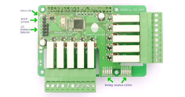
Status LED
The Status LED is located near pin 1 of the Raspberry Pi connector. The Status LED has different blinking patterns used to indicate different states of the Communication Watchdog.
With the Communication Watchdog disabled the Status LED pattern is 75ms ON, 3s OFF.
When Communication Watchdog is enabled the Status LED patters are as follows:
| Blink Pattern | State |
|---|---|
| 75ms ON, 3s OFF | RPi Communication timeout |
| 75ms ON, 75 ms OFF, 75 ms ON, 3s OFF | RPi Communication is OK |
Communication Watchdog
The communication watchdog is used to detect a communication timeout, when a timeout occurs the Status LED pattern is changed and if the I2C-HAT has Digital Output Channels(Relays, Open Collectors, etc..) the Safety Value for the outputs is loaded.
Using I2C commands you can Get/Set the Communication Watchdog Period. The Period is stored in the on-board FLASH of the I2C-HAT.
Digital Outputs
Using I2C commands you can Get/Set the Digital Output Channels states, all at once or by specific channel. There are two concepts linked to the Digital Output Channels:
- PowerOn Value – loaded at power on, after reset
- Safety Value – loaded at communication timeout
The PowerOn and Safety Values are stored in the on-board FLASH of the I2C-HAT, so they’re available at next board power-up. Get/Set commands are available for both values
Digital Inputs
Using I2C commands you can Get the Digital Input Channels states, all at once or by specific channel. Every Digital Input Channel has two Counters attached that count rising and falling edges. There are I2C commands that can Get/Reset the edge counters.
Digital Input Channels can also generate Interrupt Requests(IRQs).
Firmware Update
Firmware update is possible via I2C bus, check the I2C-HAT Firmware update post for details.